| June, 2007 | science@berkeley lab | | lab a-z index | lab home |
|
|||
| Keeping in Sync at a Quadrillionth of a Second | ||||||||||||||||||||||||||||||
| Contact: Paul Preuss, paul_preuss@lbl.gov | ||||||||||||||||||||||||||||||
Femtosecond lasers have been around since the 1980s, their pulses measured in quadrillionths of a second (10-15 second). The turn of the 21st century saw the achievement of attosecond pulses, lasting mere billionths of a billionth of a second (10-18 second). Now particle accelerators, and experiments that depend on them, are demanding precision on comparable time scales.
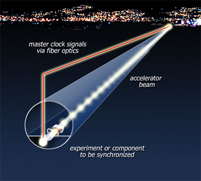
"In the new generation of accelerators, the accelerator components and accelerator diagnostics, and the time signals sent to experimenters, all have to be timed relative to one another within femtoseconds, by means of a master clock," says John Staples, a physicist in the Center for Beam Physics of the Accelerator and Fusion Research Division. "And because accelerators have large footprints, the accuracy of the clock has to be guaranteed over kilometer lengths." Compared to experiments using only lasers, this is a significantly greater challenge. "Typically a laser experiment sits on a table top, so travel times are short and the different components are not hard to synchronize," says Russell Wilcox of the Engineering Division, Staples's colleague on the stabilization system. "A two-kilometer-long accelerator is another problem altogether." A laser clockThe solution Staples and Wilcox came up with is a system that uses a near-infrared laser as the master clock, its light traveling through optical fiber of the kind developed for the telecommunications industry. "At the center of the optical fiber is a glass core made of germanium-doped quartz, nine micrometers in diameter," Staples explains. (A micrometer is one millionth of a meter.) The core, about one-tenth the diameter of a human hair, is jacketed in additional layers of undoped quartz and other protection. "The glass core is more transparent than air," Wilcox adds. "It's so transparent that the laser light propagates for many kilometers with very little loss." Transmitting the laser signal through the fiber is not a problem, but maintaining the fiber's precise length is. Temperature variations, as between daytime warmth and nighttime coolness, vary the velocity of signals through the fiber, so that they arrive too late or too early. This can throw off timing signals by large amounts. "All kinds of things affect the fiber, not just temperature," says Wilcox. "For example, optical fibers are acoustically sensitive — in fact they make good microphones. And accelerators are inherently noisy." The guarantor of precision in a clock system of this kind is the number of wavelengths (cycles) of laser light of a specific frequency in a length of fiber. By reflecting the light back on itself at the end of its journey — say, at the farthest extent of an accelerator's beam line — the light waves are made to interfere with one another and produce interference fringes, which can be counted. Any change in the length of the fiber, or other influence on the transit time, will change the number of fringes per unit length. "So we monitor the number of fringes and add or subtract length to maintain the right number," Staples says.
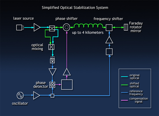
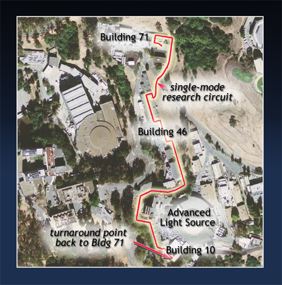
Two kinds of compensating mechanisms do the job. In one, a length of fiber is wrapped around a piezoelectric core, which changes size in response to changes in an electric field: when the core expands, the spooled fiber stretches. Although the response time is rapid, the length change is slight, adding only a few picoseconds (trillionths of a second) to the travel time along the entire length of the fiber. The other compensating method is a variable air gap. The laser light leaves the fiber and travels through open air for a few millimeters, before striking a mirror and being reflected back into the continuation of the fiber. The mirror is moved forward or back to shorten or lengthen the travel distance. The motor drive that moves the mirror is slow but can change the path length substantially. "It's a little like the spooled piezoelectric core is a tweeter, and the variable air gap is a woofer," Wilcox says. Although the "tweeter" and the "woofer" can adjust the effective length of the optic fiber, neither compensator would be adequate unless the frequency of the laser itself were kept absolutely accurate. "Otherwise you could fool yourself," Staples says. "You could keep the same number of fringes, but the length of the fiber could be changing as the frequency changes." Thus the laser frequency must be precisely maintained at its origin. This is done by passing a sample of the beam through an acetylene gas cell and tuning it to the gas's absorption line, or as Wilcox puts it, "feeling out the peak of the acetylene absorption line" — the timing system's fundamental reference. Testing the feedbackContinually compensating for distortions in the length of the fiber-optic cable is analogous to the "adaptive optics" used to keep optical telescopes in focus despite atmospheric turbulence, or the coordination of signals from multiple radio telescopes to form a synthetic aperture kilometers in diameter. "The ALMA phased-array millimeter-wave telescope under construction in the Atacama desert will have 64 separate dishes whose signals will be coordinated to provide resolution equal to the Hubble Space Telescope," Staples explains. "The signals from each dish will be sent over fiber optic cables to a central correlator. John Fox at the Stanford Linear Accelerator told us about ALMA when we were discussing ideas for the timing system of SLAC's LCLS, the Linac Coherent Light Source, and it gave us the idea for our laser-optic timing system." To test the idea, Staples and Wilcox first strung a 100-meter length of optical fiber they happened to have on hand around their lab. Indications were good, but Staples says, "What we needed was to test it in a real-world environment. What better place than a couple of kilometers of fiber optics running around Berkeley Lab, under roads, in and out of buildings and communications closets? The IR frequency we're using is in the telecommunications range, so we called up Ted Sopher and Ed Ritenour in the Information Technology Division and asked, 'Do you have an extra loop of fiber a couple of kilometers long?'"
Ritenour and Sopher identified a loop of high-speed fiber optics cable from Building 71, where Staples and Wilcox's lab is located, to Building 10, adjacent to the ALS, and back, a round-trip distance of 1.97 kilometers. They provided a "pigtail" so Staples and Wilcox could run their fiber to the nearest terminal of the communications lines. "We send the light out on the fiber and it returns to our lab 1.97 kilometers later," Staples says. "We impose a frequency shift and change polarization and reflect the light, which goes back out and returns another 1.97 kilometers later to where it originated — a total path length of 3.94 kilometers. We analyze the light upon its return and impose the corrections needed to stabilize it." Staples and Wilcox are now completing the final steps in the system. Says Wilcox, "We have the transmission medium — a stabilized optical path almost four kilometers long, accurate to within less than a wavelength." The optical carrier has been stabilized to a single optical fringe, less than five femtoseconds. "The next step is to send more complex clock signals over this path." "There is a relationship between the phase velocity and the group velocity, and we are carefully measuring the temperature variation of this difference," says Staples. "With our system the difference in velocities is about one percent, and we are measuring that one percent difference to about one percent — that is, one ten-thousandth of how the phase velocity varies with temperature." For experiments that require only narrow-band signals (those that travel at phase velocity), maintaining synchronization via compensation mechanisms has already been solved. But for experiments requiring more complex signals, temperature variations in the group velocity of the signal must also be compensated. Staples and Wilcox are currently heating and cooling a length of their stabilized optical fiber in an oven — "which we borrowed from Ellie Blakely in Life Sciences, an old friend," Staples says — to measure the group velocity's temperature dependence. "Once we conclude those experiments, we can stabilize the group velocity as well as the phase velocity in future precise-timing experiments."
Staples explains that in the finished system, the far end of a fiber, which is looped back to their lab for tests in the current setup, will go to an experiment or an accelerator component to synchronize it with all the other components. Each of these components or experiments will be on a separate fiber, "all emanating from the central laser clock in a star configuration. The central-facility laser is propagated through several optical fibers, each individually stabilized, placing the client at the end of each fiber in femtosecond-level synchronism with all the others." While the first customer for the fiber-optics based femtosecond timing system is SLAC's LCLS, the system has many other potential applications in projects on which Lab researchers are collaborating, including the FERMI free-electron laser (FEL) facility under construction at the Elettra synchrotron in Trieste, Italy; the timing systems for the proposed International Linear Collider; and, not least, the Lab's own plan to build a "FEL Farm," a linac that will power 10 free-electron lasers. Additional information
|
||||||||||||||||||||||||||||||
| Top | ||||||||||||||||||||||||||||||